In communication, it is critical to have a common language and semantics that both parties can understand for the communication to be effective. This can be thought of as having a common language when talking of human communication, and as a protocol while talking of computer networking/communications. As discussed in the previous section, with the advent of computer networking, many vendors came out with their own proprietary protocols for computers to talk to each other, leading to interoperability issues between computer systems and networking was limited to devices from the same vendor. You can't get a person who knows only Chinese to effectively communicate with a person who knows only Russian!
International bodies involved in standardization were making efforts to evolve an open common framework, which could be used by all devices that needed to communicate with each other. These efforts led to the development of a framework called the Basic Reference Modelfor Open Systems Interconnections (OSI) reference model. This was jointly developed by the International Organization for Standardization (ISO) and International Telegraph and Telephone Consultative Committee (CCITT) (abbreviated from the Comité Consultatif International Téléphonique et Télégraphique), which later became the ITU-T.
We will broadly define the OSI model in the subsequent section, and then dive deeper into the TCP/IP model that will help clarify some of the concepts that might appear vague in the OSI discussion, as the OSI model is only a reference model without any standardization of interfaces or protocols, and was developed before the TCP/IP protocols were developed.
OSI had two major components as defined in the ISO/IEC 7498-1 standard:
- An abstract model of networking, called the Basic Reference Model or seven-layer model
- A set of specific protocols defined by other specifications within ISO
Basic OSI reference model
The communication entities perform a variety of different functions during the communication process. These functions range from creating a message, formatting the message, adding information that can help detect errors during transmission, sending the data on the physical medium, and so on.
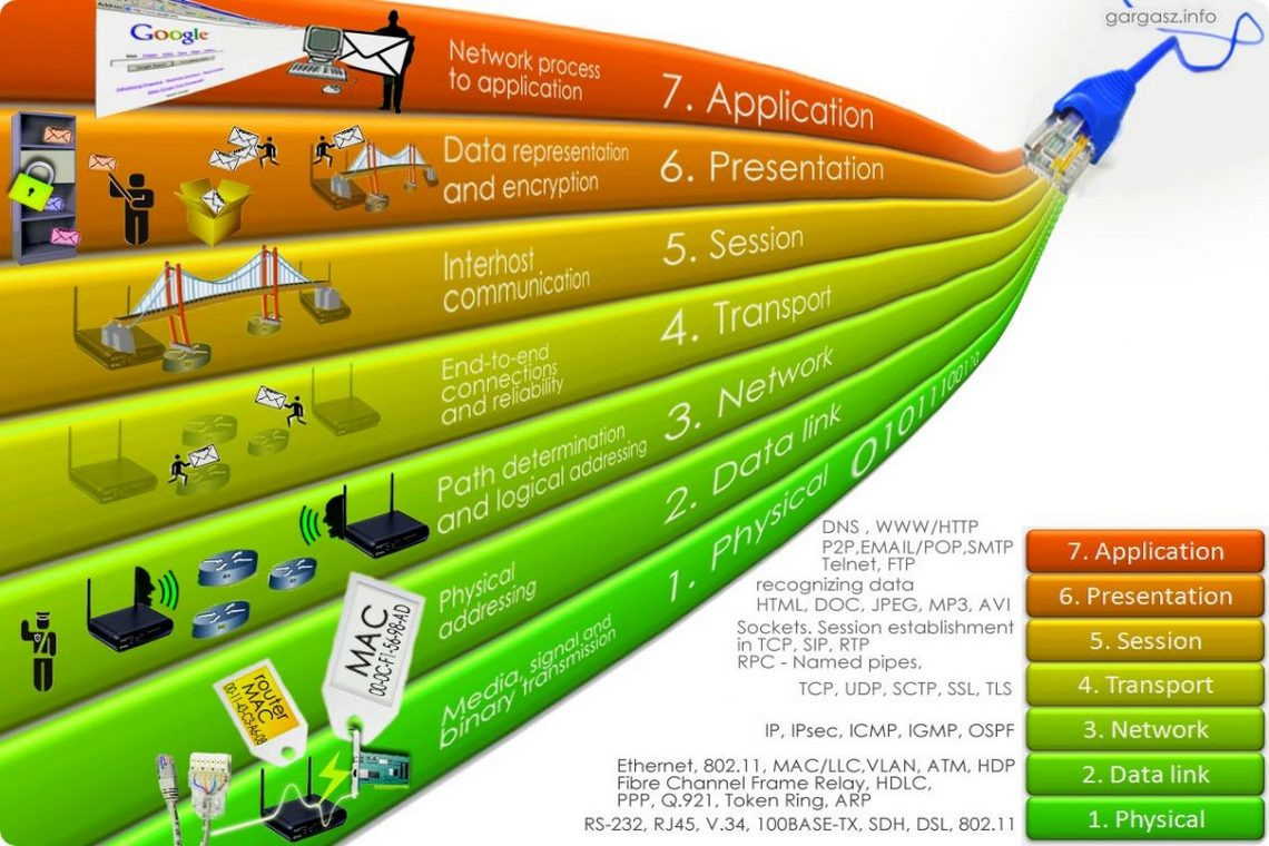
The OSI reference model defines a layered model for interconnecting systems, with seven layers. The layered approach allows the model to group similar functions within a single layer, and provides standard interfaces allowing the various layers to talk to each other.
Figure 1 shows the seven layers of the OSI model. It is important to note that the reference model defines only the functions of each layer, and the interfaces with the adjoining layers. The OSI model neither standardizes the interfaces between the various layers within the system (subsequently standardized by other protocol standards) nor delves into the internals of the layer, as to how the functions are implemented in each layer.
The OSI model describes the communication flow between two entities as follows:
- The layers have a strict peering relationship, which means that layers at a particular level would communicate with its peer layers on the other nodes through a peering protocol, for example, data generated at layer 3 of one node would be received by the layer 3 at the other node, with which it has a peering relationship.
- The peering relationship can be between two adjacent devices, or across multiple hops. As an example, the intermediate node in figure 1, that has only layers 1 through 3, the peering relationship at layer 7 will be between the layer 7 at the transmitting and receiving nodes, which are not directly connected but are multiple hops away.
- The data to be transmitted is composed at the application layer of the transmitting node and will be received at the application layer of the receiving node.
- The data will flow down the OSI-layered hierarchy from layer 7 to layer 1 at the transmitting node, traverse the intermediate network, and flow up the layered hierarchy from layer 1 to layer 7 at the receiving node. This implies that within a node, the data can be handed over by a layer to its adjacent layer only. Each layer will perform its designated functions and then pass on the processed data to the next layer:

Figure 1: The OSI reference model
The high-level functions of each layer are described as follows:
Layer 1 - The physical layer
The primary function of this layer is to convert the bit stream onto the physical medium by converting it into electrical/optical impulses or radio signals. This layer provides the physical connection to the underlying medium and also provides the hardware means to activate, maintain, and de-activate physical connections between data link entities. This includes sequencing of the bit stream, identifying channels on the underlying medium, and optionally multiplexing. This should not be confused with the actual medium itself.
Some of the protocols that have a layer 1 component are Ethernet, G.703, FDDI, V.35, RJ45, RS232, SDH, DWDM, OTN, and so on.
Layer 2 - The data link layer
The data link layer acts as the driver of the physical layer and controls its functioning. The data link layer sends data to the physical layer at the transmitting end and receives data from the physical layer at the receiving node. It also provides error detection and correction that might have occurred during transmission/reception at the physical medium, and also defines the process for flow control between the two nodes to avoid any buffer overruns on either side of the data link connection. This can happen using PAUSE frames in Ethernet, and should not be confused with flow control in higher layers.
Some of the protocols that operate at the data link layer are LAPB, 802.3 Ethernet, 802.11 WiFi and 802.15.4 ZigBee, X.25, Point to Point (PPP) protocol, HDLC, SLIP, ATM, Frame Relay, and so on.
Layer 3 - The network layer
The basic service of the network layer is to provide the transparent transfer of datagrams between the transport layers at the two nodes. This layer is also responsible for finding the right intermediate nodes that might be required to send data to the destination node, if the destination node is not on the same network as the source node. This layer also breaks down datagrams into smaller fragments, if the underlying datalink layer is not capable of handling the datagram that is offered to the network layer for transport on the network.
A fundamental concept in the OSI stack is that data should be passed to a higher layer at the receiving node as it was handed over to the lower layers by the transmitting peer. As an example, the TCP layer passes TCP segments to the IP layer, and the IP layer might use the services of the lower layers, leading to fragment packets on the way to the destination, but when the IP layer passes the data to the TCP layer at the receiving node, the data should be in the form of TCP segments that were handed down to the IP layer at the transmitting end. To ensure this transparent transfer of datagrams to the receiving node TCP layer, the network layer at the receiving node reassembles all the fragments of a single datagram before handing it over to the transport layer.
The OSI model describes both connection-oriented and connectionless modes of the OSI network layer.
Connection- oriented and connectionless modes are used to describe the readiness of the communicating nodes before the process of actual data transfer between the two nodes. In the connection-oriented mode, a connection is established between the source and the destination, and a path is defined along the network through which actual data transfer would happen. A telephone call is a typical example of this mode, where you cannot talk until a connection has been established between the calling number and the called number.
In the connectionless mode of data transfer, the transmitting node just sends the data on the network without first establishing a connection, or verifying whether the receiving end is ready to accept data, or even if the receiving node is up or not. In this mode, there is no connection or path established between the source and the destination, and data generally flows in a hop by hop manner, with a decision being taken on the best path towards the destination at every hop. Since, data is sent without any validation of the receiving node status, there is no acknowledgement of data in a connectionless mode of data transfer. This is unlike the connection-oriented mode, where the path is defined the moment a connection is established, and all data flows along that path, with the data transfer being acknowledged between the two communicating nodes.
Since data packets in a connection-oriented mode follow a fixed path to the destination, the packets arrive in the same sequence at the receiver in which they were transmitted. On the other hand, packets in the case of a connectionless network might reach the receiver out of sequence if the packets are routed on different links on the network, as decisions are taken at every hop.
The OSI standard defined the network layer to provide both modes. However, most of the services were implemented in practice as the connectionless mode at layer 3, and the connection-oriented aspects were left to layer 4. We will discuss this further during our discussion on TCP/IP.
Some of the protocols that operate at the network layer are AppleTalk, DDP, IP, IPX, CLNP, IS-IS, and so on.
Layer 4 - The transport layer
The transport layer provides the functional and procedural means of transferring variable-length data sequences from a source to a destination host via one or more networks. This layer has end-to-end significance and provides a connectionless or connection-oriented service to the session layer. This layer is responsible for connection establishment, management, and release.
The transport layer controls the reliability of a given link through end-to-end flow control, segmentation/de-segmentation, and error control. This layer also provides multiplexing functions of multiplexing various data connections over a single network layer.
Some protocols operating at the transport layer are TCP, UDP, SCTP, NBF, and so on.
Layer 5 - The session layer
The primary purpose of the session layer is to coordinate and synchronize the dialog between the presentation layers at the two end points and to manage their data exchange. This layer establishes, manages, and terminates connections between applications. The session layer sets up, coordinates, and terminates conversations, exchanges, and dialogues between the applications at each end.
Some of the protocols operating at the session layer are sockets, NetBIOS, SAP, SOCKS, RPC, and so on.
Layer 6 - The presentation layer
The presentation layer provides a common representation of the data transferred between application entities, and provides independence from differences in data representation/syntax. This layer is also sometimes referred to as the syntax layer. The presentation layer works to transform data into the form that the application layer can accept. This layer is also responsible for encryption and decryption for the application data.
Some examples of protocols at the presentation layer are MIME, ASCII, GIF, JPEG, MPEG, MIDI, SSL, and so on.
Layer 7 - The application layer
The application layer is the topmost layer of the OSI model, and has no upper-layer protocols. The software applications that need communication with other systems interact directly with the OSI application layer. This layer is not to be confused with the application software, which is the program that implements the software; for example, HTTP is an application layer protocol, while Google Chrome is a software application.
The application layer provides services directly to user applications. It enables the users and software applications to access the network and provides user interfaces and support for services such as email, remote file access and transfer, shared database management, and other types of distributed information services.
Some examples of application layer protocols are HTTP, SMTP, SNMP, FTP, DNS, LDAP, Telnet, and so on.
The TCP/IP model
The Advanced Research Projects Agency Network (ARPANET), which was initially funded by the US Department of Defense (DoD) was an early packet-switching network and the first network to implement the protocol suite TCP/IP. ARPANET was the test bed of the TCP/IP protocol suite which resulted in the TCP/IP model also known as the DoD model.
The TCP/IP model is a simplified model of the OSI model and has only four broad layers instead of the seven layers of the OSI model. Figure 2 shows the comparison between the two models. As can be seen from the following figure, the TCP/IP model is a much more simplified model, where the top three layers of the OSI model have been combined into a single application layer, and the physical and data link layers have been combined into a network access layer:

Figure 2: Comparing the OSI model with TCP/IP model
Some of the major differences between the two models are as follows:
- The functions of the application layer in the TCP/IP model include the functions of the application, presentation and session layer of the OSI model
- The OSI session layer function of graceful close/end-to-end connection setup, management, and release is taken over by the TCP/IP transport layer (Transmission Control Protocol)
- The network access layer combines the functions of the OSI data link and the physical layers
- The network layer in the OSI mode can be connection oriented or connectionless, while the Internet Protocol (IP) is a connectionless protocol
- The transport layer in the OSI model is connection oriented, whereas, different protocols at the transport layer in the TCP/IP model provide different types of services; for example, TCP provides a connection oriented service, while UDP provides a connectionless service
Let's explore what happens when data moves from one layer to another in the TCP/IP model taking Figure 3 as an example. When data is given to the software application, for example, a web browser, the browser sends this data to the application layer, which adds a HTTP header to the data. This is known as application data. This application data is then passed on to the TCP layer, which adds a TCP header to it, thus creating a TCP segment. This segment is then passed on to the network layer (IP layer) where the IP header is added to the segment creating an IP packet or IP datagram. This IP header is then encapsulated by the data link adding a data link header and trailer, creating a Frame. This frame is then transmitted onto the transmission medium as a bit stream in the form of electrical/optical/radio signals depending upon the physical media used for communication:

Figure 3: Data flow across the TCP/IP layers
A simplified stack showing some protocols in the TCP/ IP stack is shown in the following figure:

Figure 4: Common protocols in the TCP/IP stack
Let's delve deeper into the TCP/IP model by looking at the TCP/IP headers in some more detail.