This chapter provides information and commands concerning the following topics:
Connecting a Rollover Cable to Your Cisco Router or Switch
Figure 1 shows how to connect a rollover cable from your PC to a router or switch.
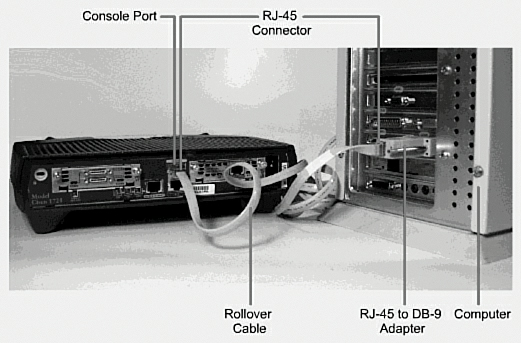
Figure 1 Rollover Cable Connection
Using a USB Cable to Connect to Your Cisco Router or Switch
On newer Cisco devices, a USB serial console connection is also supported. A USB cable (USB type A to 5-pin mini type B) and operating system driver are needed to establish connectivity. Figure 2 shows a Cisco device that can use either a mini-USB connector or a traditional RJ-45 connector.
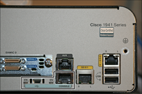
Figure 2 Different Console Port Connections
Note
Only one console port can be active at a time. If a cable is plugged into the USB port, the RJ-45 port becomes inactive.
Note
The OS driver for the USB cable connection is available on the Cisco.com website.
Terminal Settings
Figure 3 illustrates the settings that you should configure to have your PC connect to a router or switch.
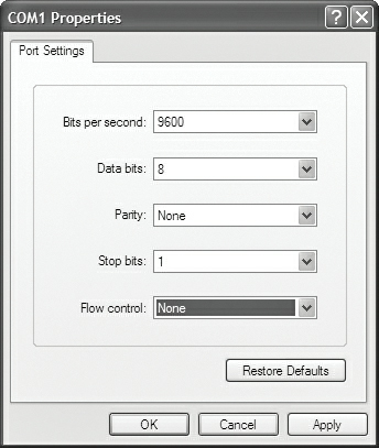
Figure 3 PC Settings to Connect to a Router or Switch
LAN Connections
Table 1 shows the various port types and connections between LAN devices.
Table 1 LAN Connections
Port or Connection | Port Type | Connected To | Cable |
Ethernet | RJ-45 | Ethernet switch | RJ-45 |
T1/E1 WAN | RJ-48C/CA81A | T1 or E1 network | Rollover |
Console | 8 pin | Computer COM port | Rollover |
Console | USB | Computer USB port | USB |
AUX | 8 pin | Modem | RJ-45 |
Serial Cable Types
Note
As I mentioned in the article “Variable Length Subnet Masking (VLSM),” most networks today no longer use serial connections between routers; Ethernet connections are faster and are now the de facto standards for interconnecting devices. I use serial connections in my Portable Command Guides to differentiate between point-to-point connections and LAN connections. Places that use older equipment for their hand-on labs may use serial connections. While not part of the new CCNA 200-301 exam objectives, I am showing this information in this guide to assist those readers using older equipment as part of their learning experience.
Figure 4 shows the DB-60 end of a serial cable that connects to a 2500 series router.
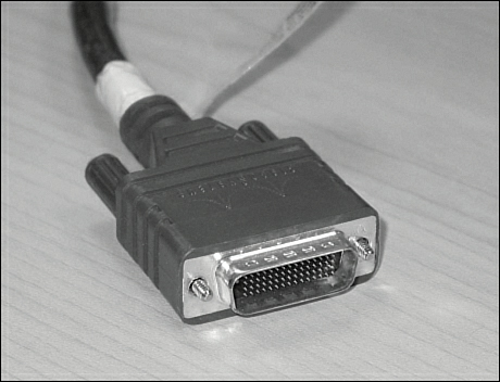
Figure 4 Serial Cable (2500 Series)
Figure 5 shows the newer smart serial end of a serial cable that connects to a smart serial port on your router. Smart serial ports are found on modular routers, such as the newest ISR series (4xxx), older ISR series (x9xx), (x8xx), or on older modular routers such as the 17xx or 26xx series. Smart serial ports on modular routers have to be purchased and installed separately, and are not part of the baseline configuration. Figure 2 shows a smart serial card installed into the EHWIC 0 slot on a 1941 series router.
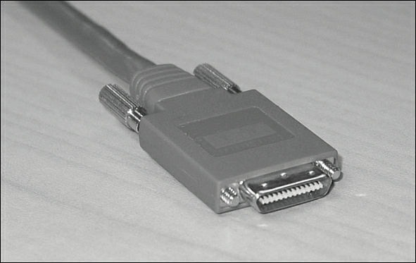
Figure 5 Smart Serial Cable (17xx, 26xx, ISR 18xx, 19xx, 28xx, 29xx, 4xxx)
Figure 6 shows examples of the male DTE and the female DCE ends that are on the other side of a serial or smart serial cable.
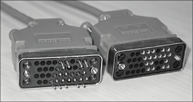
Figure 6 V.35 DTE and DCE Cables
Most laptops available today come equipped with USB ports, not serial ports. For these laptops, you need a USB-to-serial connector, as shown in Figure 7.
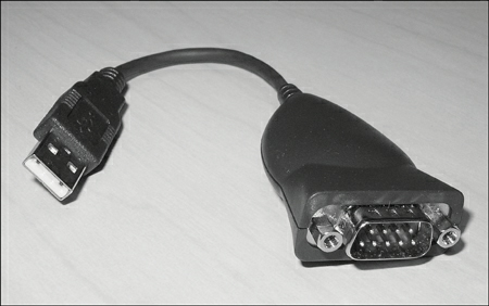
Figure 7 USB-to-Serial Connector for Laptops
Figure 8 shows an example of a USB type A to 5-pin mini type B cable used for connecting a PC/laptop with a USB port to the USB port on a Cisco device.
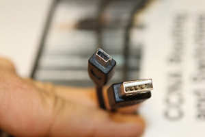
Figure 8 USB Type A to 5-Pin Mini Type B Cable
Which Cable to Use?
Table 2 describes which cable should be used when wiring your devices together. It is important to ensure you have proper cabling; otherwise, you might be giving yourself problems before you even get started.
Table 2 Determining Which Cables to Use When Wiring Devices Together
If Device A Has a: | And Device B Has a: | Then Use This Cable: |
Computer COM/Serial port | RJ-45 Console of router/switch | Rollover |
Computer USB port | USB Console of router/switch | USB type A to 5-pin mini type B with appropriate OS drivers |
Computer NIC | Switch | Straight-through |
Computer NIC | Computer NIC | Crossover |
Switch port | Router’s Ethernet port | Straight-through |
Switch port | Switch port | Crossover (see CAUTION below table) |
Router’s Ethernet port | Router’s Ethernet port | Crossover |
Computer NIC | Router’s Ethernet port | Crossover |
Router’s serial port | Router’s serial port | Cisco serial DCE/DTE cables |
Caution
Most switches now have the ability to autosense which type of cable is plugged into a port, and will make the appropriate connection through software to ensure communication occurs. This autosensing of cable types can be disabled. It is therefore recommended to use a crossover cable when connecting two switches via Ethernet ports, to ensure the path of communication is created.
Table 3 lists the pinouts for straight-through, crossover, and rollover cables.
Table 3 Pinouts for Different Cables
Straight-Through Cable | Crossover Cable | Rollover Cable |
Pin 1 – Pin 1 | Pin 1 – Pin 3 | Pin 1 – Pin 8 |
Pin 2 – Pin 2 | Pin 2 – Pin 6 | Pin 2 – Pin 7 |
Pin 3 – Pin 3 | Pin 3 – Pin 1 | Pin 3 – Pin 6 |
Pin 4 – Pin 4 | Pin 4 – Pin 4 | Pin 4 – Pin 5 |
Pin 5 – Pin 5 | Pin 5 – Pin 5 | Pin 5 – Pin 4 |
Pin 6 – Pin 6 | Pin 6 – Pin 2 | Pin 6 – Pin 3 |
Pin 7 – Pin 7 | Pin 7 – Pin 7 | Pin 7 – Pin 2 |
Pin 8 – Pin 8 | Pin 8 – Pin 8 | Pin 8 – Pin 1 |
ANSI/TIA Cabling Standards
ANSI/TIA-568 is a set of telecommunications standards that addresses commercial building cabling for telecommunications products and services. The current standard is revision D (2017), which replaced the 2009 revision C, the 2001 revision B, the 1995 revision A, and the initial issue of T568 in 1991. All of these past revisions and the initial issue are now obsolete.
T568A Versus T568B Cables
One of the most known and discussed features of the ANSI/TIA-568 standard is the definition of the pin assignments, or pinouts, on cabling. Pinouts are important because cables do not function properly if the pinouts at the two ends of a cable are not matched correctly. There are two different pinout assignments: T568A and T568B.
The difference between these two standards is pin assignments, not in the use of the different colors (see Table 4). The T568A standard is more compatible with voice connections and the Universal Service Order Codes (USOC) standard for telephone infrastructure in the United States. In both T568A and USOC standards, the blue and orange pairs are now on the center four pins; therefore, the colors match more closely with T568A than with the T568B standard.
So, which one is preferred? Information from the standards bodies on this matter is sketchy at best. T568B was traditionally widespread in the United States, whereas places such as Canada and Australia use a lot of T568A. However, T568A is now becoming more dominant in the United States, too.
There is no hard-and-fast rule about which standard to use. It will usually depend on the company you work for and their preferences. Just be consistent. If you are on a job site that uses the B standard, then continue to use B; as I previously mentioned, the A standard more closely aligns with traditional telephone infrastructure, so some installers prefer the A standard.
T568A Standard | T568B Standard | ||||||
Pin | Color | Pair | Description | Pin | Color | Pair | Description |
1 | White/green | 3 | RecvData + | 1 | White/orange | 2 | TxData + |
2 | Green | 3 | RecvData – | 2 | Orange | 2 | TxData – |
3 | White/orange | 2 | TxData + | 3 | White/green | 3 | RecvData + |
4 | Blue | 1 | Unused | 4 | Blue | 1 | Unused |
5 | White/blue | 1 | Unused | 5 | White/blue | 1 | Unused |
6 | Orange | 2 | TxData – | 6 | Green | 3 | RecvData – |
7 | White/brown | 4 | Unused | 7 | White/brown | 4 | Unused |
8 | Brown | 4 | Unused | 8 | Brown | 4 | Unused |
Tip
Odd pin numbers are always the striped wires.
Tip
A straight-through (patch) cable is one with both ends using the same standard (T568A or T568B). A crossover cable is one that has T568A on one end and T568B on the other end.
Tip
A rollover (console) cable (used in connecting a PC/laptop to a console port on a Cisco device) is created if you flip the connector (the modular plug) upside down on one side. I have seen many students create a rollover cable in my classes; unfortunately, the assignment was to create a straight-through patch cable, so one end had to be cut off and a new modular plug had to be aligned properly and crimped.

