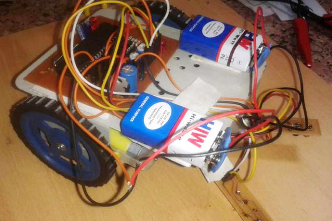
An edge avoider robot is very like my past undertaking "Line Follower Robot". This 8051 microcontroller based robot recognizes an edge and dodges it by turning or halting. Let us perceive how might we plan an edge avoider robot without any problem.
Idea of Edge Avoider Robot
Idea of Edge Avoider robot is same as line supporter. In these sorts of robots, we for the most part use conduct of light at high contrast surface. At the point when light fall on a white surface it will practically full reflects and if there should be an occurrence of dark surface light is consumed by dark surface. This conduct of light is utilized in a line devotee robot just as edge avoider robot.
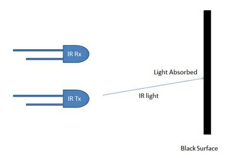
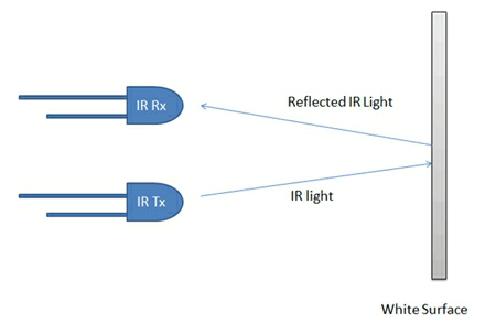
Here we have utilized IR transmitter and collector likewise called photograph diodes are utilized for sending and getting light. IR transmits infrared lights. At the point when infrared beams falls on any surface with the exception of dark or much dull surfaces, it's reflected back and catched by photodiode and produces some voltage changes. At the point when IR light falls on dark surface, light is consumed by the dark surface along with no beams reflect back, resultantly photograph diode doesn't get any light or beams.
Here in this Edge Avoider robot when sensor detects white surface then microcontroller gets 0 as info and when detects dark line controller gets 1 as information.
Circuit Diagram and Working Explanation
We can devide the Edge Avoider Robot venture into three distinct segments that are sensor segment, control segment and driver area.
Sensor area: This segment contains IR diodes, potentiometer, Comparator (Op-Amp) along with LEDs. Potentiometer is utilized for setting reference voltage at comparator's one terminal and IR sensors are utilized to detect the line and give an adjustment in voltage at comparator's subsequent terminal. At that point comparator analyzes the two voltages and creates a computerized signal at yield. Here in this circuit we utilizes 2 comparators for 2 sensors. LM 358 is utilized as comparator. LM358 has inbuilt 2 low clamor Op-amp.
Control Section: 8051 microcontroller is utilized for controlling entire the procedure of line supporter robot. The yields of comparators are associated with pin number P0.0 and P0.1 of 8051. 8051 peruses these signs and send orders to driver circuit to drive line devotee .
Driver segment: Driver segment comprises engine driver and two DC engines. Engine driver is utilized for driving engines in light of the fact that microcontroller doesn't gracefully enough voltage and ebb and flow to drive the engine. So we add an engine driver circuit to get enough voltage and ebb and flow for engine. Microcontroller sends orders to this engine driver and afterward it drive engines.
Working
Working of this edge avoider robot is very intriguing and same as line supporter however contrast in the tasks in case detecting inputs. In this robot when it detects white surface it goes ahead along with when any of sensors or the two sensors sense no sign or dark surface it gets stop along with go in reverse along with modify its course and if again it sense white surface than go ahead.
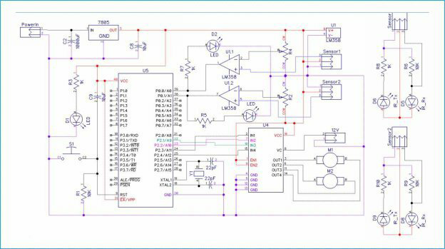
Circuit graph is appeared for this edge avoider robot. Yield of comparators is straightforwardly associated with pin number P0.0 and P0.1 of microcontroller. Furthermore, engine driver's information pin 2, 7, 10 and 15 is associated at pin number P2.3, P2.2, P2.1 and P2.4 individually. What's more, one engine is associated at yield pin of engine driver 3 and 6 and another engine is associated at 11 and 14.
In programming most importantly we have characterized info and yield pins. And afterward in fundamental capacity we checked sources of info and sends yield as needs be to yield pins for driving engine. There are four conditions in this edge avoider that we read by utilizing 8051 microcontroller. We have utilized two sensors to be specific left sensor and right sensor.
Conditions:
Input | Output | Movement Of Robot | ||||
Left Sensor | Right Sensor | Left Motor | Right Motor | |||
LS | RS | LM1 | LM2 | RM1 | RM2 | |
0 | 0 | 1 | 0 | 1 | 0 | Forward |
0 | 1 | 1 | 0 | 0 | 0 | Stop/back/Turn Right |
1 | 0 | 0 | 0 | 1 | 0 | Stop/back/Turn Left |
1 | 1 | 0 | 0 | 0 | 0 | STOP/back/turn left |
We have writen program as per above table conditions.
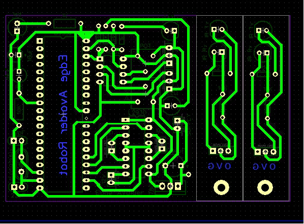
PCB Layout
Code
#include<reg51.h>
sbit ls=P0^0;
sbit rs=P0^1;
void delay(unsigned int time)
{
unsigned i,j;
for(i=0;i<time;i++)
for(j=0;j<1275;j++);
}
#define motor P2
#define forward 0x06
#define backward 0x09
#define turn_left 0x04
#define turn_right 0x02
#define stop 0x00;
void main()
{
    while(1)
    {
     if(ls && rs)
         motor=forward;
     if(!ls && rs)
     {
         motor=stop;
         delay(200);
         motor=turn_left;
         delay(200);
     }
     if(ls && !rs)
     {
         motor=stop;
         delay(200);
         motor=turn_right;
         delay(200);
     }
     else
     {
         motor=stop;
         delay(200);
         motor=turn_left;
         delay(200);
     }
  }
}

